This post is part of the overall MS-700 Exam Study Guide. Links to each topic as they are posted can be found here.
In this post I will go through the following topics relating to network planning for Microsoft Teams.
- Configure Tenant Data Upload in Microsoft Call Quality Dashboard
- Configure reporting labels for Microsoft Teams
- Assess network readiness by using Microsoft 365 network connectivity test and dashboard
- Configure QoS port range and DSCP markings
In Part 1 of this post, we looked at getting started with network planning for Microsoft Teams.
Configure Tenant Data Upload in Microsoft Call Quality Dashboard
The Teams Call Quality Dashboard (CQD) is a great resource to get a view of the performance of Teams for your users. The CQD gives granular details of each call and meeting made to provide visibility of the quality of each connection and the underlying factors that contributed to any issues experienced. For example, a user reporting poor Teams call quality could be down to poor network quality, poor WiFi connection, incorrectly configured firewall / proxy / VPN setup, out of date device firmware, out of date Teams client etc.
The CQD allows us to see each of these factors and visualize what happened during a particular call and correlate with other similar calls. A large number of reports from a single physical location for instance, will show in the CQD and allow admins to quickly identify the root cause of the issue as site network related. While a trend of users experiencing issues with a particular model of speakerphone can help narrow down a device firmware issue.
The benefits of the CQD can be enhanced by telling it more about the environment using the tenant data upload functionality. Using tenant data upload, information about the physical locations (buildings) and devices (endpoints) in your environment can be imported into the CQD to provide additional context and clarity to the results.
To get started, open the Teams CQD and click the “Settings” icon at the top right, then select “Tenant Data Upload”. On the upload page there are two options presented as mentioned above: “Building” and “Endpoint”. To generate the building or endpoint files, follow the format described in the documentation here. You can also download a sample building file here.
In Figure 1 you can see an example CSV file of a simple building data file describing one office. Note that I have added headings to make the image easier to understand but the headings should be removed before uploading.

The last three columns are Boolean values (where 0 is false and 1 is true) which denote if the network is:
- InsideCorp: Inside the corporate network
- ExpressRoute: Connected via ExpressRoute
- VPN: A VPN network
The fields that are required in the file are:
- NetworkIP
- NetworkName
- NetworkRange
- BuildingName
- InsideCorp
- ExpressRoute
Any others, while recommended, can be left blank.
Once the file is populated and the header row is not present, it can be uploaded to the CQD for processing.
Note: As networks are identified as subnets, generic subnets such as 192.168.0.0/24 may cause unreliable results due to how common these network ranges are. It’s recommended where possible, to avoid using these common subnets in production.
For the Endpoint data file, Figure 2 shows a sample CSV defining endpoints – as before this shows the header row but this needs to be removed before upload. Ideally this data can be extracted from your existing asset management or CM system. Note that in the file the endpoint name column must be unique.

The columns “EndpointLabel1/2/3” can be used to assign labels to machine types to identify them more easily but are not required.
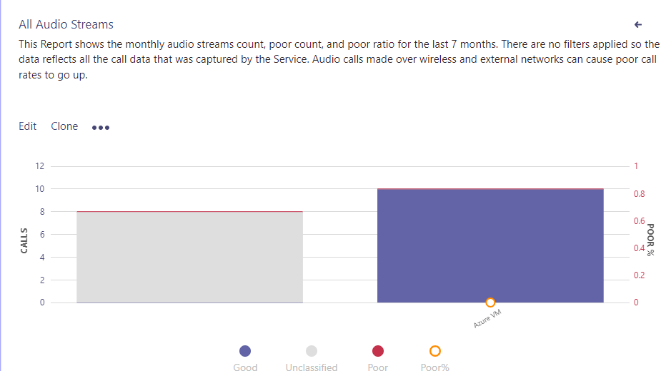
With this data uploaded, reports created in the CQD will return this additional information. For example, a simple report on call quality based on the label assigned to endpoints is shown in Figure 3.
Configure reporting labels for Microsoft Teams
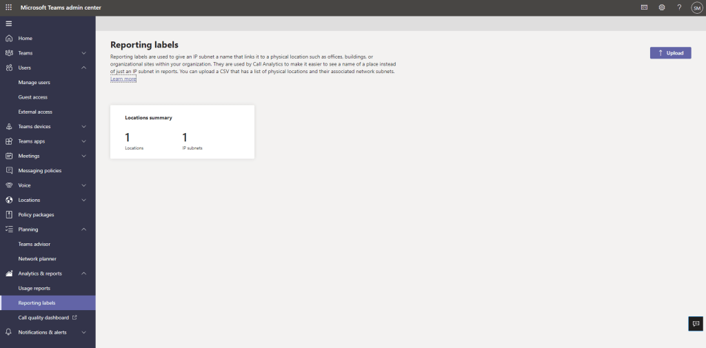
Very similar to the building data file upload for the CQD, reporting labels are a way of associating networks with your physical locations within the Teams Admin Center (TAC). Once uploaded, the location names will be supplied for admins who are viewing call analytics for users within the TAC.
To configure reporting labels, you can use the same file formate as the building data upload and upload it in the TAC under “Analytics & Reporting” -> “Reporting Labels” as shown in Figure 4.
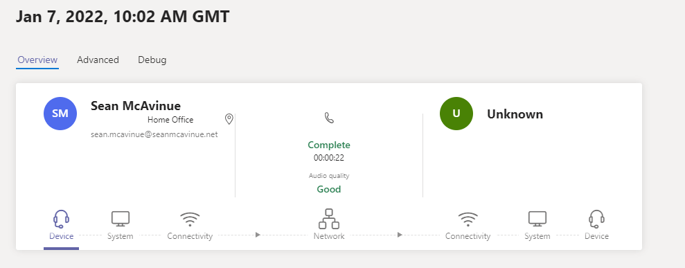
With the data uploaded. Make some test calls from your defined locations and under the users call analytics, the location tag will be shown for the networks that the user has called from (Figure 5)
Assess network readiness by using Microsoft 365 network connectivity test and dashboard
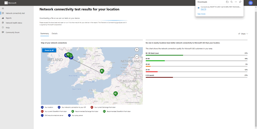
The Microsoft 365 Network Connectivity Test is a great resource to ensure that your corporate network is configured optimally for Microsoft 365 services, including Teams. To run the test, navigate to the connectivity test page and click “Run test” under the “Network connectivity test” tab. Make sure you are logged in to your tenant so the data is saved there.
The test consists of some browser tests and a downloadable JavaScript tool. The browser will need permissions to view your location to determine your connectivity status and when the initial tests run a file will download as shown in Figure 6.

Run the downloaded app and wait for the tests to finish then click close (Figure 7). Note: You may be prompted by Windows Firewall to allow traffic for the tests to run.

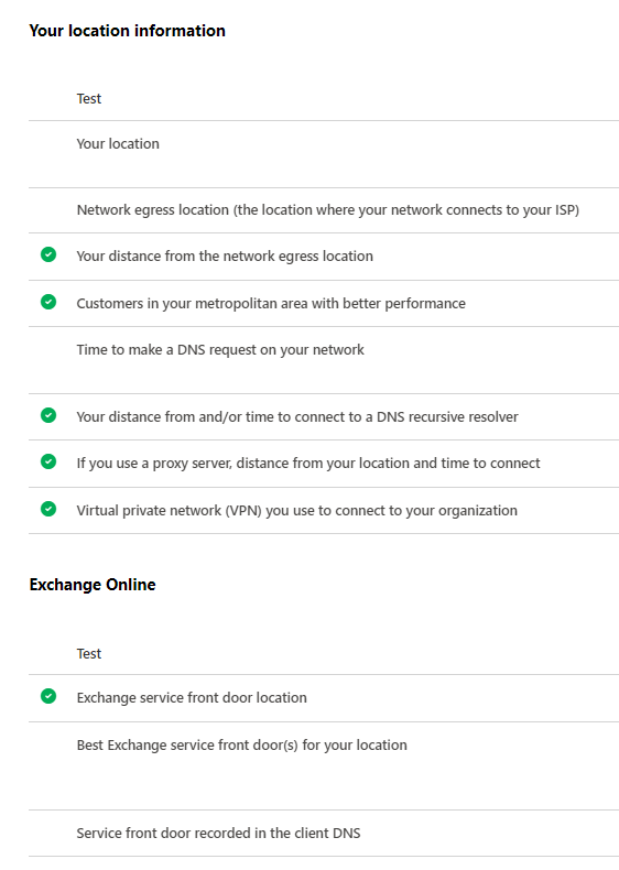
When the tests are complete, the report will be available under the “Reports” tab of the connectivity test page. Any potential issues with your connection to Microsoft 365 services will be detailed here. In figure 8, I show a sample of the results but I have omitted a lot of information specific to my connection.
Configure QoS port range and DSCP markings
Quality of Service (QoS) and DSCP markings allow network devices to identify and prioritize particular traffic on a network. QoS is generally used for traffic that is sensitive to latency or packet drops, a common example of this is voice and video traffic. To be clear, Teams does not require any QoS configuration to work, however on complex or congested networks, where prioritization of traffic is required to make sure everything runs smoothly, QoS can be configured to decorate the traffic from Teams clients. For QoS to be effective you will also need to configure QoS on your network devices as appropriate. Network device configuration is not in scope of this exam but each manufacturer will have their own instructions for this.
There are two methods available to apply QoS to Microsoft Teams traffic. It can be applied using port-based tagging which prioritises traffic based on particular ports or by using a Group Policy Object to insert QoS DSCP markers into the traffic. Port-based tagging is universal to Windows, Linux and Mac however DSCP via GPO can obviously only be deployed to domain joined Windows machines. The recommendation would be to use a combination of both methods to ensure optimal coverage of QoS across the network.
Port-based QoS should be configured on your network devices and to prioritize traffic based on the ports and DSCP values detailed in Table 1.
| Media traffic type | Client source port range | Protocol | DSCP value | DSCP class |
| Audio | 50,000-50,019 | TCP/UDP | 46 | Expedited Forwarding (EF) |
| Video | 50,020-50,039 | TCP/UDP | 34 | Assured Forwarding (AF41) |
| Application / Screen sharing | 50,040-50,059 | TCP/UDP | 18 | Assured Forwarding (AF21) |
The ports listed above can be changed via the Teams Meeting Settings in the TAC as shown in Figure 9. The DSCP values cannot be changed.

To apply policy-based QoS tagging on a single Windows machine, the following PowerShell commands will configure the QoS Policy.
##Configure Audio Policy
New-NetQosPolicy -Name "Teams Audio" -AppPathNameMatchCondition "teams.exe" -IPSrcPortStartMatchCondition 50000 -IPSrcPortEndMatchCondition 50019 -DSCPAction 46

##Configure Video Policy
New-NetQosPolicy -Name "Teams Video" -AppPathNameMatchCondition "teams.exe" -IPSrcPortStartMatchCondition 50020 -IPSrcPortEndMatchCondition 50039 -DSCPAction 34

##Configure Application and Screen Sharing Policy
New-NetQosPolicy -Name "Teams Application-Screen Sharing" -AppPathNameMatchCondition "teams.exe" -IPSrcPortStartMatchCondition 50040 -IPSrcPortEndMatchCondition 50059 -DSCPAction 18
To configure a GPO to apply DSCP markers to traffic from domain joined machines, a new Computer GPO is required with the “Policy-based QoS” option configured as detailed here.
Summary
This post concludes the “Plan and configure network settings for Microsoft Teams” section of the study guide. Planning appropriately for the network considerations of Teams may not be the most exciting thing in the world but is key to providing a good user experience.
In the next section I will look at the licensing requirements for Microsoft Teams.
